
Mouse Control in Revit
Revit has different functions associated with aspects of the mouse. Below is a list of those functions.
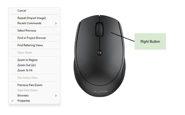
Clicking the right button brings up the above dialog box. Personally, I find this function useful when location an item in the project browser.

Clicking the left button allow you to select items in Revit. Holding the control key while clicking with the left button allows you to select multiple items. Holding the shift key while clicking with the left button allows you to deselect items.

Using the mouse’s scrolling wheel allows to zoom in and out while in Revit. Holding down the wheel allows you to pan across the page. Holding the control key while using the wheel also allows you to zoom in and out.

Troubleshooting : No Dialog box appears after clicking the “Select Views / Sheets” button when printing in Revit
Go to the View Tab
User Interface
Browser Organization

2. In the Browser Organization dialog box go to sheets tab
3. Select sheet prefix

4. OK

Creating a Barreled Ceiling
While in the section view where you want the barreled ceiling to be located at
Architecture tab
Build section
Select down arrow on the Component function
Select Model in Place
Please note this function is not available on Revit LT
Select ceilings in the family category and parameters
Name ceiling
Extrusion
Pick a Plane
Select wall perpendicular to barreled ceiling
Draw arch using draw tool
Close the extrusion
Green Check Mark
Green Check Mark Finish Model
Adjust Ceiling as needed

Custom family : Making materials changeable in model (Type Parameter)
Open Family
Modify tab
Select family types dialog box

4. Select Now

5. In the Parameter Properties dialog box
Name Parameter Material
Under Data Type select Material
Select Instance

6. Select OK
7. Select OK
8. In the 3D View select the extrusion you want to change materials on
9. Select associated family parameters in the properties tab
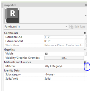
10. Select Materials
11. OK
12. Ensure that Subcategory is None
13. Load family into project
Void Sweeps in Families (Beveled Edge)
After drawing the shape in which you want to have a beveled edge in. Extrude set backs in which the void sweep should start

2. Create
3. Void Forms
4. Void Sweeps
5. Pick Path
6. Select the setback created
Ensure that the sweep path is closed
7. To draw the sweep profile ensure that the profile is < by sketch >

8. Edit Profile
9. Draw profile in which you want voided
10. Select green check mark
11. Select green check mark
12. Delete setback
Door hardware in 3D view
The door families already loaded in Revit have door hardware already loaded in the family.
The hardware is only visible in detail level : fine.
Changing the detail level to fine will also allow the door hardware to appear in Enscape.
Handles on refrigerators and dishwashers will also appear in detail level fine
Adding Mullions to Windows and Doors
Select door or window that you want to add mullions to
Edit family
Elevation
Interior or exterior
Depending on which side of the window / door you are working on
Set
Pick a plane
OK
Select glass plane that you want to add mullion to
Model Line
Draw that mullions on the window
Modify tab
Align tool
Align modify lines to the edge of the glass and lock it in place
Note: This will not show up on Enscape

Creating custom paint colors and painting
Go to manage tab
Select Materials in setting tab
Select new materials

4. Create new materials
5. Default new materials should generate
6. Rename new materials to desired paint color name
7. In appearance table select color

8. Sherwin Williams list the RGB value of each color. Enter the RGB value of desired color

9. OK
10. Apply
11. OK
12. Modify tab
13. Select paint

14. Search desired color
15. In floorplan view select walls you want painted
You can also use the paint tool to apply different materials to a wall without changing the materials of the wall.
Please note the painted color / materials will not show up in Enscape if the wall is in existing phase.

Room Schedule SF Grand Total
When the Room schedule is open, select sorting / grouping on the properties tab
Check grand totals
Select title and totals in the drop down menu
Select formatting tab
Select Area
Calculate totals

7. OK

Adjust the order of a Revit Schedule
While the room schedule is open, select the sorting / grouping on the properties tab

2. Sort by: Number
3. Ensure ascending is selected

Color Schemes
Useful if you want to change the color of your drawing space
File
Options
Colors
Under Canvas colors
Canvas color schemes:
Chose your preferred light or dark

Phasing / Creating a Demo Sheet
I recommend setting up phasing before drawing anything in the project. Bonus points if you set if up in your template.
Select Manage Tab
In the Phasing section select Phases
Phasing box should open
Insert new phase between existing and new construction
Name new phase as DEMO

5. Select Graphics Overrides
6. Change the dashed lines for the demolished phase status to red dashed lines

7. Select OK
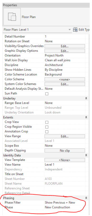
8. You can ensure that you are in the correct phasing on the properties parameters box under phasing tab
9. Draw the existing floorplan in the Phase Filter and Phase
Phase Filter = Show All
Phase = Existing
10. After drawing the existing floor plan, you should create a DEMO View
Duplicate view
Duplicate with detailing
Rename new View to DEMO
EX: Level 1 DEMO
Change Phasing to below Phase Filter and Phase
Phase Filter = Show previous + Demo
Phase + New Construction
11. Change phasing in original view to below Phase Filter and Phase
Phase Filter = Show Previous + New
Phase = New Construction
12. To DEMO an item in the drawing (There are alternative ways to demolish an item. This is my preferred way)
Select the item that needs to be demolished
Change phasing to the below phase
Phase Created = DEMO
Phase Demolished = New Construction
13. If you set up the DEMO sheet and New Construction plan correctly, the demolished item should disappear from the New Construction plan and appear on the DEMO plan in red dashed lines.
14. When drawing New Construction items ensure you are in the below phasing
Phase Created = New Construction
Phase Demolished = None
15. You can check to see if you phased correctly by doing the following
Ensure you are in view with new construction phase
Turn off the thin line
New construction phase should be bold black lines
Existing construction phase should be thin gray lines
Demo phase should be red dashed lines
Bonus: Image from my trip to Iceland

Changing Dimensions / Rounding
Useful when you want to easily read dimensions in a project
Annotate tab
Under dimension section select down arrow

3. Linear Dimension Types
4. Under the primary units section select the box next to unit format
5. Units : feet and fractional inches or fractional inches
6. Rounding : to the nearest 1/4” (or to your desired rounded dimension)

Callouts / Crop Views
There are two ways to focus the view on a specific portion of the model
Callouts
View tab
Callout
Found in the create portion of the tab
Create box around portion of model you want to view
Right click the callout and select go to view or in project browser open the call out you created
Crop View
Duplicate the view in which you want to see a portion of
Remain the view
Turn on crop region visible in the properties parameter box under extents

4. Use the crop region to section off area in which you want to focus on
5. Select crop view and unselect crop region visible
Bonus: Image from my trip to Iceland

Underlay
Useful when aligning upper and lower floors when drawing existing buildings.
Useful when doing designing lighting plans on reflected ceilings, to know what is on the floorplan.
Found on the properties browser under underlay
You can select base and top viewing range and view orientation


Room Schedules
View Tab
Schedules found in the create tab
Schedules / Quantities
Select Rooms under category
Ensure you are creating the schedule with the correct construction phase
OK
Move over the following fields into the
Number
Name
Area
Please note that you have to create room tags , and name them on the floorplan for this information to show up on the room schedule
8. If you want to separate the room schedule by levels
Duplicate schedule
Rename to corresponding level
Open schedule properties
Fields tab
Add levels
Filter tab
Filter by level
Filter by corresponding level
Bonus: Image from my trip to Colorado

Design Options
Design Option is useful when you want to create multiple design layouts for one space. Please note that this is not available on Revit LT.
Manage Tab
Design Options
Design Options
Option Set
New

5. You can create as many option that you want under Option

6. You can switch between the different design option while in the new construction view. Located on the bottom tool bar in Revit, select what option you want to view

Please note that you cannot adjust the rest of the model while in a view, you have to return to the main model to adjust view.
Please note, detailed lines and annotated text will not save in the different option, you have to convert the detail lines to model lines and use model text for the different options.
Bonus: Image from my trip to Iceland

Filled Region
Useful to add 2D texture or to call out a specific area
Annotate tab
Region
Found in Detail section
Filled region
Draw the area in which you want to fill in and select what texture / color you want to use
Bonus: Image from my trip to Iceland

Loading Families
Revit provides a wide range of families that you can plug into your model. You can load them into the project be doing the below:
Insert Tab
Load Autodesk Family
After finding family that you need, select load
If you can not find a family that you need already loaded into Revit, below are some sites to look at:
BIM objects
Revit City
Kohler
Plumbing
Lighting
Brizo
Plumbing
Herman Miller
Furniture
Subzero - Wolf
Appliances
Bonus - Image from my trip to Iceland

Saving PDF as Arch D
Ensure the view you want saved is on an appropriately sized Sheet
File
Export
PDF
Name the PDF
File
File Name
Last Name of client
Place PDF in preferred location
File
Location
Select Browse
Browse for folder box should open
select desired folder
Ensure correct paper size is selected
Size
Paper size
Arch D: 24x36
Paper Placement
Offset from corner
No Margin
Zoom
Size
Zoom
Zoom: 100%
If only one sheet is needed for the PDF hit OK
If multiple sheets are needed for the PDF:
Export Range
Selected views/ sheets
Select pencil button
Select sheets needed for PDF
Select
If new Sheets set needed to be created
Create new empty set (page with explosion in corner)
Select sheets needed for PDF
Select
OK
Bonus: Image from my trip to Iceland - Sun Voyager